Leave Your Message

Why Is Splicing Metal Studs Important?

Why Is Splicing Metal Studs Important?

Splicing Metal Studs is more than joining two short framing members. It creates a continuous load path when a single stud cannot reach the required height. This matters on tall walls, renovation projects, and sites with limited material lengths. A weak splice can cause twisting, local buckling, uneven finishes, or unexpected movement around openings.

Roger LaBoube, a respected cold-formed steel researcher and educator, emphasized, “Good design begins with understanding how the load travels.” That principle applies directly to Splicing Metal Studs. The splice must transfer axial loads, lateral forces, and sometimes impact from construction activity. Installers usually align overlapping studs carefully, use the specified screws, and follow the manufacturer’s spacing requirements. The overlap length also matters. So does the stud thickness.

Small details matter.

A reliable splice should remain straight under handling, resist separation, and avoid creating a hard spot in the wall surface. Engineers may also check deflection, connection strength, corrosion protection, and compatibility with sheathing. Site conditions can complicate the work. Damp areas, damaged flanges, rushed measurements, or missing bridging may reduce performance.

The imperfect part is common: drawings may show the connection clearly, yet field crews still interpret it differently. That gap deserves attention. A professional review should compare the design, product data, local requirements, and actual installation. Splicing Metal Studs works best when planning and workmanship support each other, rather than relying on screws alone.
Why Is Splicing Metal Studs Important?

What Splicing Metal Studs Means in Modern Wall Framing

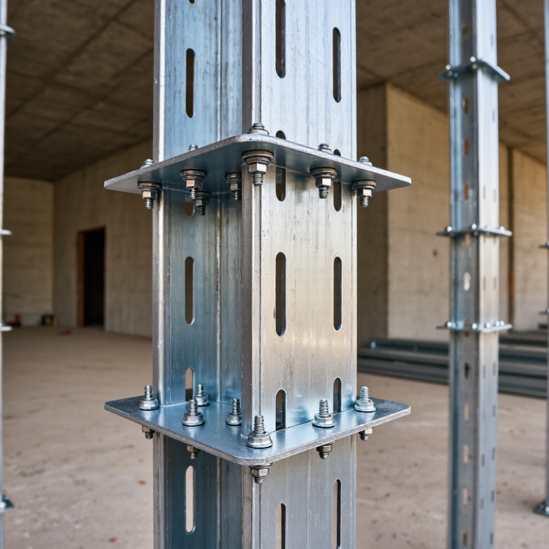
Splicing metal studs means joining two shorter steel sections to create one continuous framing member. In modern wall framing, this solves transport, storage, and height problems without changing the wall layout. The joint is not merely a connection. It becomes part of the load path. That distinction matters.

On site, installers may use a matching stud, a track sleeve, or back-to-back sections, depending on the engineered detail. Fasteners must reach both pieces, remain properly spaced, and avoid crushing the thin steel. The splice should be placed away from concentrated loads when the design permits. Edges need alignment. A crooked joint can twist drywall, disturb insulation, and create a visible bulge. For load-bearing walls, splice location, screw pattern, and section thickness should come from project calculations, not guesswork. Non-load-bearing partitions still need secure joints near doors, corners, and ceiling tracks.

Reliable work begins with clean cuts, dry surfaces, and a quick inspection for burrs or deformation. A level and straightedge reveal problems that a rushed visual check may miss. The awkward truth is that a neat-looking splice can still be weak. A useful field lesson is to question convenient fixes when a longer stud is unavailable. One small omission can cause movement months later. Months later, one missing screw may appear as a drywall crack beside a door.
How Proper Splicing Improves Structural Strength and Stability

Why Is Splicing Metal Studs Important?

Proper splicing improves the structural strength and stability of connected metal studs. A well-designed splice transfers axial, shear, and bending forces through a continuous load path. The AISI S240 standard requires structural cold-formed steel framing connections to be checked for these actions. This matters when walls carry floor loads, roof reactions, or strong wind pressure. A splice can look neat and still be weak.

Overlap length, screw spacing, and fastener edge distance control performance. AISI S100 design procedures consider local buckling, distortional buckling, and connection resistance. These failure modes may appear suddenly around a poorly supported joint. In practice, installers should align stud flanges carefully and keep the splice away from openings when possible. A small offset can create eccentric loading. That detail is easy to miss.

Tips: Use the project engineer’s approved splice detail. Confirm the stud thickness before selecting fasteners. Keep overlapping sections tightly seated. Check every screw for full penetration and proper spacing. Do not rely on extra screws to repair poor alignment. Measure twice. Inspect once more.

A useful field record includes stud size, thickness, splice location, fastener type, and inspection results. The American Iron and Steel Institute emphasizes documented design assumptions and connection verification in its cold-formed steel standards. Site conditions may differ from drawings, so the splice should be reviewed when loads, openings, or framing supports change. Perfect installation is rarely achieved, but careless assumptions should never become the design method.

Key Factors That Determine the Best Splicing Method

Why Is Splicing Metal Studs Important?

Choosing the best splicing method starts with the stud’s role. A non-load-bearing partition needs different treatment from a framed wall carrying ceiling loads. Check the drawings, stud gauge, wall height, and expected movement before cutting metal. Local building codes and project specifications should guide the final decision. A quick shortcut can create a weak joint.

Overlap length is a major factor. Longer overlaps usually distribute forces more evenly, but they may interfere with services inside the wall. Fastener type, spacing, and edge distance also matter. Screws should sit firmly without stripping the thin steel. For heavier framing, a manufactured sleeve or reinforced channel may provide better alignment than simple end-to-end contact. Keep the splice straight. Even small twists can affect board installation.

Site conditions can change the plan. Limited access may make one-sided fastening necessary. Moisture, vibration, and temperature movement can also influence the connection. I have seen clean-looking splices fail because the surrounding track was poorly anchored. That mistake is easy to miss. Measure twice, and inspect both sides when possible. Photographs and installation records improve accountability, especially when several crews share the work. When the load path is unclear, ask a qualified structural professional to review the detail before installation. The best method is not always the fastest one.

Why Is Splicing Metal Studs Important? - Key Factors That Determine the Best Splicing Method

Splicing Method Typical Use Main Structural Benefit Key Design Inputs Important Limitations Relative Suitability
Nested Stud Sleeve Extending a stud by inserting a matching or compatible stud section inside the existing member. Provides alignment and can create a continuous load path when the sleeve length and fastener pattern are engineered correctly. Stud depth, flange width, steel thickness, splice location, axial load, lateral load, and required overlap. There is no universal overlap length or screw pattern; local buckling and connection failure must be checked. High for aligned extensions
Back-to-Back Studs Joining two stud sections with their webs or flanges arranged back-to-back. Increases local stiffness and provides a wider connection surface for fasteners, blocking, or supported components. Combined member geometry, screw spacing, eccentricity, load direction, stud thickness, and required bracing. May increase wall thickness and weight; insufficient fastening can cause separation, slip, or local distortion. High for concentrated loads
Lapped Stud Sections Overlapping two sections along their length where a continuous member is difficult to transport or install. Distributes force over a longer connection zone and can reduce abrupt stiffness changes at the splice. Required lap length, screw edge distance, screw spacing, shear transfer, axial force, and connection slip. A long lap does not automatically provide adequate capacity; fastener tear-out and bearing must be verified. Medium to high
Web or Flange Reinforcement Plate Reinforcing a splice, opening, point load, or connection zone with a separate steel plate or strap. Improves local load distribution and helps resist web crippling, fastener pull-out, or flange distortion. Plate thickness, width, length, fastener type, edge distance, load magnitude, and corrosion compatibility. A plate is normally a reinforcement component, not a complete splice solution unless the connection is specifically designed. Medium; detail-dependent
Engineered Connector or Sleeve Projects requiring a documented, repeatable connection for load-bearing or high-performance framing. Allows the connection capacity, fastener arrangement, and installation sequence to be defined in one approved detail. Design loads, tested capacity, steel grade, coating, connector geometry, fastener schedule, and installation tolerances. The connector must match the stud profile and project requirements; field modifications can invalidate the design. Very high when approved
Full-Length Stud Replacement Situations where the splice cannot be reliably designed, inspected, or installed within the available space. Eliminates the splice interface and generally provides the most straightforward continuous load path. Available member length, handling limits, wall height, deflection requirements, and installation access. May increase material waste, handling effort, and transportation difficulty. Highest when practical
Key Factors That Determine the Best Splicing Method
Load Type Axial compression, tension, shear, bending, and combined loading produce different demands at the splice. Axial load and lateral load should be established before selecting the connection. A method suitable for a non-load-bearing partition may be inadequate for a load-bearing wall or support condition.
Stud Geometry Depth, flange width, lip configuration, and section shape control fit, stiffness, and connection access. Common cold-formed steel thicknesses are often approximately 0.45–1.20 mm, but project specifications govern. A sleeve or reinforcing piece must physically fit without damaging the protective coating or reducing the effective section.
Splice Location Splices near openings, supports, floor lines, or concentrated loads experience higher connection demands. Locate the splice away from critical zones when permitted by the structural design. Moving the splice can be more effective than adding reinforcement, provided continuity and height requirements remain satisfied.
Fastener Performance The connection may fail through pull-out, pull-over, shear, bearing, tear-out, or excessive slip. Fastener diameter, length, spacing, edge distance, steel thickness, and corrosion resistance must be compatible. Screw quantity alone does not determine capacity; the complete connection detail must be checked.
Deflection and Stability The splice must maintain alignment and prevent local buckling, twisting, or excessive wall movement. Check stud slenderness, bracing, wall height, spacing, serviceability limits, and sheathing contribution. A strong splice can still perform poorly if the overall stud is inadequately braced.
Installation and Inspection The best method must be practical to install accurately within the available access and tolerances. Confirm overlap, alignment, fastener placement, member identification, and site access before installation. Poor alignment or missing fasteners can reduce the intended capacity even when the selected method is technically suitable.
Compliance and Verification Load-bearing splices should follow the applicable building code, project specification, and approved structural detail. Verify material grade, thickness, connection capacity, fire requirements, and corrosion protection. Where no standard detail applies, a qualified structural professional should design or approve the splice.

Note: Overlap lengths, fastener spacing, member thickness, and load capacities are project-specific and should be determined from the applicable code, approved design, and verified structural calculations.

Common Problems Caused by Incorrectly Spliced Metal Studs

Why Is Splicing Metal Studs Important?

Common Problems Caused by Incorrectly Spliced Metal Studs

Incorrectly spliced metal studs can weaken an entire wall assembly. The problem often begins with a rushed overlap or poorly placed fasteners. When stud ends do not align correctly, loads may transfer unevenly through the frame. This can create twisting, bowing, or visible movement around doors and windows. Small errors become expensive after gypsum panels conceal the framing.

In field inspections, a common finding is a splice secured with too few screws near a service opening. That location reduces stiffness and allows the joint to flex during panel installation. Workers may also use mismatched stud sizes, leaving one flange unsupported. The result can include cracked joints, uneven surfaces, squeaking, and loose trim. It may not fail immediately. That is the danger.

A reliable splice needs proper overlap, aligned flanges, and fasteners suited to the framing thickness. Follow the project drawings and applicable structural requirements. Check the joint before closing the wall. Push the stud lightly and watch for rotation or movement. Measure the face with a straightedge. Visual alignment alone can be misleading. Rechecking takes minutes. Repairing concealed framing takes much longer.

How to Inspect and Maintain Spliced Metal Stud Connections

Why Is Splicing Metal Studs Important?

How to Inspect and Maintain Spliced Metal Stud Connections

Spliced metal studs transfer loads through overlapping sections, fasteners, and connected tracks. A weak splice can create movement, cracking, or local buckling. In practice, a clean-looking splice can still be incorrectly fastened. Inspectors should compare every connection with approved drawings and AISI S240-20 or applicable design requirements.

Check the splice location, overlap length, stud alignment, and screw spacing. Look for missing fasteners, stripped screw heads, oversized holes, sharp distortion, and visible gaps. A laser level can reveal slight movement that is difficult to see by eye. Touch the connection carefully. A loose vibration deserves attention.

The 2023 U.S. Bureau of Labor Statistics report recorded 1,075 construction fatalities, with a 9.6 fatality rate per 100,000 full-time workers. Safe access and stable temporary support matter during every inspection.

Tips: Photograph both sides of each splice. Record the date, location, fastener count, and observed damage. Check again after impact, water exposure, or major building movement. Remove surface corrosion only when approved repair procedures allow it. Do not add random screws as a repair. That may hide the real problem.

One inspection weakness is relying too heavily on appearance. Splices should be reviewed by qualified personnel, especially when they support ceilings, partitions, or structural framing. Small details matter.