Global infrastructure is expanding, and cable management is becoming a reliability decision, not merely a purchasing detail. MarketsandMarkets and Grand View Research both identify steady growth in the global cable tray market, driven by data centers, renewable energy, industrial automation, and utility projects. Their findings also highlight stronger demand for corrosion-resistant materials in harsh operating environments.
That shift explains the growing interest in Frp Cable Tray systems. Fiber-reinforced plastic trays can resist salt spray, moisture, many chemicals, and electrical conductivity concerns. In a coastal substation, for example, a pultruded tray may face humid air, chemical residue, and intense ultraviolet exposure every day. Resin selection, glass-fiber content, load rating, span distance, and fire performance still matter. FRP is not automatically superior.
Dr. Vistasp M. Karbhari, a widely recognized FRP researcher, has offered a practical warning: “FRP is not maintenance-free; it is maintenance-different.” That idea should guide global buyers. A low purchase price may hide weak supports, poor UV protection, or incomplete testing documents. Sometimes, the cheapest option becomes the most expensive mistake.
This guide examines leading Frp Cable Tray manufacturers for international buyers. It considers manufacturing experience, certification evidence, product consistency, customization capability, delivery performance, and after-sales support. Standards, test reports, and traceable technical data deserve close attention. Marketing language does not replace proof.
The comparison will not pretend that one manufacturer fits every project. Climate, installation method, cable weight, and local engineering requirements change the decision. That is the uncomfortable part. Reliable procurement requires questions before quotations, not after installation.
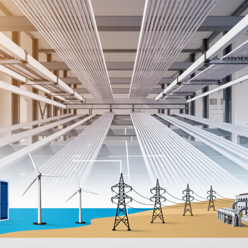
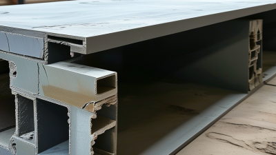
FRP cable trays combine glass fibers with a polymer resin, usually polyester, vinyl ester, or epoxy. The resin controls chemical resistance, while the fibers provide stiffness and load capacity. MarketsandMarkets reports that the global fiber-reinforced polymer composites market is expected to grow at over 7% annually through 2028. This expansion reflects demand from energy, infrastructure, and corrosive industrial sites. However, composite quality varies widely. Resin selection, fiber orientation, UV protection, and manufacturing control deserve close inspection.
Common tray types include ladder, perforated, solid-bottom, and channel designs. Ladder trays support heavy cables and improve ventilation. Solid-bottom trays offer stronger cable protection but may retain heat. Buyers should verify working load, span distance, deflection, fire behavior, and temperature limits. IEC 61537 provides requirements for cable tray systems, while NEMA VE 1 addresses construction and performance considerations. Independent test reports should show results under realistic loading, not only laboratory conditions. A larger tray is not automatically safer.
Tips: Check load data at the planned support spacing. Request salt-spray, water-absorption, and UV-aging results. Confirm that fittings use compatible materials. For fire performance, review the exact test method and rating. No single test tells the whole story. In practice, installation errors can weaken an excellent tray system, so site training and inspection remain essential.
For global buyers, IEC 61537 is more than a compliance label. It provides a common method for evaluating cable tray and ladder systems. The standard considers defined loads, support spans, and installation conditions. Manufacturers should state safe working load, not simply maximum breaking capacity. Safe working load reflects a practical limit for engineers and installers. Small detail, but important.
During testing, a tray is installed over specified spans and loaded in a controlled manner. Engineers record vertical deflection, permanent deformation, and visible damage. These results support declared load and testing classifications. A heavier tray is not automatically safer. Support spacing, couplers, fasteners, and cable arrangement can change performance. That is often missed. IEC 61537 does not replace project-specific engineering.
When comparing manufacturers, buyers should request test reports, load tables, material details, and installation assumptions. Check whether the reported safe working load matches the actual span on site. Outdoor projects also require attention to corrosion, temperature, and water exposure. I have seen designs rely on catalog figures without reviewing joint behavior. The calculation looked precise, but the evidence was incomplete. A careful review should question both the number and the test setup.
| Buyer Evaluation Dimension | Typical FRP Cable Tray Data | IEC 61537 Relevance | What Global Buyers Should Request | Verification Method |
|---|---|---|---|---|
| Product scope | Ladder tray, ventilated tray, solid-bottom tray, channel tray, bends, tees, reducers and covers | IEC 61537 covers cable tray systems and cable ladder systems, including associated fittings and supports | A complete system rather than straight tray sections only | Review product drawings, fitting catalogues and installation instructions |
| Common tray widths | Approximately 100–1,000 mm; frequently specified sizes include 150, 300, 450, 600 and 900 mm | The standard does not prescribe one universal tray width range | Confirm usable internal width, cable fill allowance and fitting compatibility | Compare certified dimensional drawings with the cable schedule |
| Common side-rail depths | Approximately 50–200 mm, depending on width, span and required load capacity | Depth is a design parameter; load performance must be established for the complete configuration | Request section dimensions and load tables for each depth | Check cross-section drawings and independent load-test records |
| Typical support spans | Common engineering spans are about 1.5, 2.0, 2.4 and 3.0 m; longer spans require specific engineering validation | Safe working load and deflection are evaluated against the stated support arrangement and span | The exact span, support type, joint location and fitting arrangement used for testing | Match the project support layout to the test configuration |
| Safe Working Load (SWL) | Often published in kN/m or kg/m; practical project values vary widely with width, depth, span and tray construction | IEC 61537 uses the declared safe working load as the basis for mechanical load evaluation | A load table showing SWL at every proposed span, including fitting and joint conditions | Check test loading, permanent deformation and residual performance after testing |
| Load calculation basis | Cable weight plus tray, cover, accessories, clamps, ice, wind or other project-specific imposed loads | The declared load must represent the complete installed system and its intended support conditions | Design assumptions, load combinations and allowable utilization ratio | Have the load schedule reviewed by the project structural or electrical engineer |
| Deflection reporting | Report actual measured deflection in millimetres at the stated SWL and support span; no single value applies to every tray design | IEC 61537 evaluates deformation during mechanical testing; buyers should not rely on SWL alone | Maximum vertical and lateral deflection, measurement points and acceptance criteria | Compare the test report with the project’s allowable appearance and clearance limits |
| Joint and fitting strength | Joint plates, splice connectors and fittings can reduce capacity if not designed for the specified span | Mechanical performance applies to the system configuration, not just an isolated straight section | Load data for straight sections, joints, bends, tees, reducers and covers | Request configuration-specific test evidence and installation torque values |
| FRP material system | Glass-fibre reinforcement in a thermosetting resin matrix, commonly polyester, vinyl ester or epoxy | IEC 61537 focuses on system performance; resin and reinforcement selection must support the declared application | Resin type, glass-fibre form, fibre content, curing process and laminate or pultrusion details | Review technical data sheets, material declarations and sample-section inspection |
| Corrosion resistance | FRP is commonly selected for coastal, chemical-processing, wastewater and offshore environments | Corrosion performance is application-dependent and should be supported by material and environmental testing | Chemical exposure list, temperature, salt or humidity conditions and expected service life | Request chemical-resistance data for the actual resin system, not generic FRP claims |
| UV and weathering performance | Outdoor FRP systems may use UV-resistant resin, surface veil or a protective coating | Outdoor durability is not established by load testing alone | UV exposure method, colour stability, surface degradation limits and maintenance requirements | Review accelerated-weathering results and project-specific environmental qualifications |
| Fire behaviour | Flame-retardant FRP grades are available; performance depends on resin, additives, geometry and test method | Fire-related properties must be declared against the specific applicable test and classification requirement | Flame propagation, smoke and fire-performance reports where required by the project | Confirm the exact standard, specimen orientation and product construction in the report |
| Electrical continuity | FRP is electrically non-conductive and does not provide metallic bonding continuity | Electrical continuity requirements are relevant to conductive systems; FRP installations require separate earthing and bonding decisions where applicable | Insulation, separation, bonding and lightning-protection requirements for the installation | Obtain an electrical design review rather than assuming tray material determines the earthing method |
| Impact and handling resistance | Pultruded and moulded FRP products have different impact behaviour and damage modes | Mechanical impact testing is separate from uniformly distributed load testing | Impact test method, energy level, temperature and acceptance criteria | Inspect samples after impact and verify that damaged sections are not accepted for installation |
| Temperature range | Project-specific FRP systems commonly require service-temperature qualification from approximately −40°C to +100°C or higher | Mechanical capacity and resin durability can change with temperature; the declared range must be supported by evidence | Continuous and intermittent temperature limits for the selected resin and tray design | Check temperature-conditioned test data and the manufacturer’s installation limitations |
| Compliance documentation | Technical drawings, load tables, installation manual, material declarations and test reports | A valid declaration should identify the tested product, support span, loading arrangement and applicable IEC 61537 requirements | Traceable reports covering the same profile, fittings, accessories and production method as the offered product | Check report dates, laboratory identity, sample identification and consistency with the purchase specification |
Note: IEC 61537 does not create one universal load value or one universal deflection limit for every cable tray. Safe working load and deflection must be assessed for the declared tray construction, support span, joint arrangement, fittings and installation conditions.
Top FRP Cable Tray Manufacturers for Global Buyers
Key FRP Data: 25–30% Glass Fiber, Corrosion Resistance, and Service Life
Many FRP cable trays contain approximately 25–30% glass fiber by weight. This reinforcement improves stiffness while keeping the tray lighter than steel. The ACMA Composites Manufacturing Handbook links fiber content, resin selection, and production quality to structural performance. Buyers should request batch test records, not rely on a catalog percentage.
FRP also resists moisture, salt spray, and many industrial chemicals. That advantage matters in coastal substations, wastewater plants, and chemical processing areas. IEC 61537 provides relevant performance testing for cable management systems, including load and mechanical behavior. However, corrosion resistance is not unlimited. Strong solvents, ultraviolet exposure, poor supports, or trapped water can shorten service life. Field studies commonly place well-designed FRP systems beyond 20 years, but actual service life depends on resin chemistry, loading, temperature, and installation quality. That estimate needs caution. A serious supplier should provide accelerated aging results, flame-performance data, dimensional tolerances, and documented load testing for each profile.
Key FRP Data: 25–30% Glass Fiber, Corrosion Resistance, and Service Life
Typical FRP cable trays use approximately 25–30% glass fiber by weight, providing structural reinforcement and dimensional stability. In suitable corrosive environments, FRP systems are commonly specified for a reference service life of about 20–30 years. Actual performance depends on resin formulation, UV exposure, temperature, load, installation quality, and maintenance conditions.
When global buyers compare FRP cable tray manufacturers, they should inspect more than price and catalog images. Resin type, glass-fiber content, load capacity, and UV resistance directly affect service life. A reliable supplier provides test reports with batch numbers, testing dates, and laboratory details. In project reviews, small documentation gaps often create bigger delays than expected.
Certifications require careful comparison. Check whether the manufacturer follows ISO 9001 for quality management and whether the tray system has been tested against IEC 61537 or relevant regional standards. For fire performance, request clear evidence under the specified ASTM or UL test method. Do not accept “certified material” as proof of a certified complete system. The wording matters.
Tips: Ask for a sample, full technical datasheet, installation guide, and recent inspection record. Compare test conditions with your project environment, including salt spray, moisture, temperature, and chemical exposure. Also review warranty exclusions. They can be surprisingly broad. A factory may appear highly qualified, yet its certification scope might exclude the tray width, resin grade, or connection hardware you need. This is easy to miss, and even experienced buyers sometimes overlook it.
For global buyers, selecting an FRP cable tray manufacturer requires more than comparing catalog prices. Regional screening should begin with verified production capacity, not stated annual output. Ask for production lines, mold availability, monthly tonnage, and recent shipment records. A factory with 200 tons of capacity may still miss deadlines during peak seasons. Production depth matters.
Export compliance needs equal attention. Request material safety data, test reports, packing specifications, and documents matching the destination market. Confirm resin type, glass-fiber content, flame performance, and UV resistance. Check whether certificates cover the actual models, not similar samples. Customs delays often start with inconsistent product descriptions or missing origin details. This is where careful review builds trust. Yet paperwork alone proves little. An on-site audit, video inspection, or independent laboratory check can expose weak controls. No screening method is perfect.
Tips: Compare quoted lead times with production schedules and port cutoffs. Request a sample order before approving volume shipments. Measure tray width, thickness, surface finish, and joint fit on arrival. Keep written approval records. Leave buffer days for tooling changes, weather, and inspections. The fastest promise may not be the most reliable choice. Ask how delays are reported, and test that answer early.